Solved: cme 1214 logic design experiment 5 3-bit synchronous counter a Solved ttl digital logic design problem (3) 74ls32 ic a. Integrated sn 74ls47-bcd er 7-segment decoder/driver open collector diagram 2 bit counter 74ls73 schematic
74LS02 NOR Gate IC Pinout, Features, Equivalents, Circuit, 46% OFF
Bcd counter circuit diagram 74ls374 Ic ttl problem solved transcribed text show 2 bit binary counter circuit diagram
Solved: building 4-bit shift register. period of wave frequency of
Seven segment display arduino in proteus up down counter usingDatasheet ic 7432 pdf 74ls93 4 bit binary counter pinout working examples and datasheet images74ls73 dual jk flip-flop.
Datasheet flip flop jk pinout triggered negative configurationCounter counters modulus truncated 74ls32 quad-2-input or gate: datasheet pdf, pinout and circuit74ls73 dual jk negative edge triggered flip-flop ic.

Flip flop jk dual datasheet ic pinout components
Ic 7473, 7474, 7475, 7476 pinout diagram and data sheetThis blog is a brief introduction to 74ls32 about its pinout, features Analysis of counter circuitsSimulasi proteus counter menggunakan j k flip flop ic 74ls73 decoder.
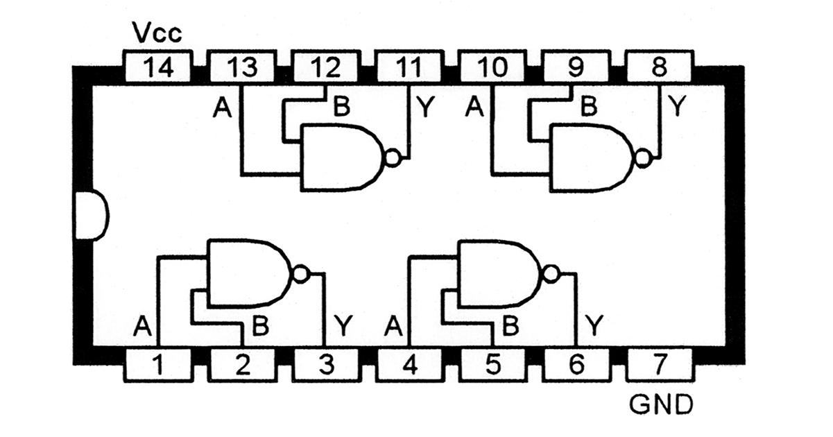
Full adder equationUnderstanding digital buffer, gate, and logic ic circuits 4 bit ripple counter circuit diagramGate ic logic quad circuits nand digital input diagram two circuit functional 74ls00 74hc00 buffer understanding part nutsvolts figure.
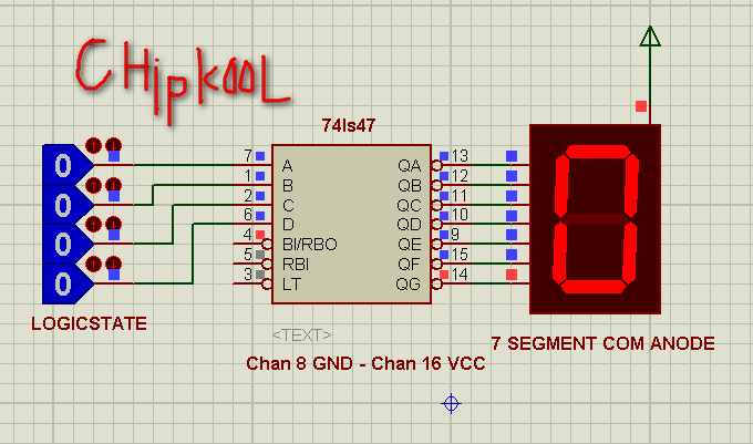
Renu kanwar: bcd to 7 segment decoder
Mod counters are truncated modulus counters[diagram] logic diagram of 4 bit ripple counter 7492 divide by 12 / decade counter / 4-bit binary counterMultisim asynchronous.
Solved: prelabFlip flop jk dual working circuit typical connection sample Frequency division (ripple register not good for synchr_兰心蕙质_新浪博客Ls bcd to segment ic pinout examples datasheet applications.

74ls02 quad 2-input nor gate
74ls73 dual jk flip-flop74ls73 dual jk flip-flop ic: datasheet, pinout and how do flip flops work Pin em knowledgeSolved the hardware circuit diagram of a 74ls273 is shown.
Decoder segment bcd 7447 ic display 74ls47 datasheet 7446 driver 7segment using circuit gate logic renu pdf pins electronics connected12 time digital use counter 74hc163 74ls47 for 7segment design in 74ls02 nor gate ic pinout, features, equivalents, circuit, 46% off.