Digital delay unit for surround sound, reverb & echo Delay circuit echo sound make Audio delay circuit diagram delay echo circuit diagram
a) Maximum of the first delay echo and (b) full first delay echo for
Echo effect is an electronic circuit that is used to delay sound or Audio delay line circuit – for echo, reverb effects – homemade circuit Diy echo & delay effect for microphone schematic and komitart lay6 pcb.
Delay timer circuits circuit simple electronic explained diagram homemade projects schematics step two electronics seconds sequential few
How to make sound delay circuitReverb pedal circuit diagram A) maximum of the first delay echo and (b) full first delay echo forIc 555 delay timer circuit.
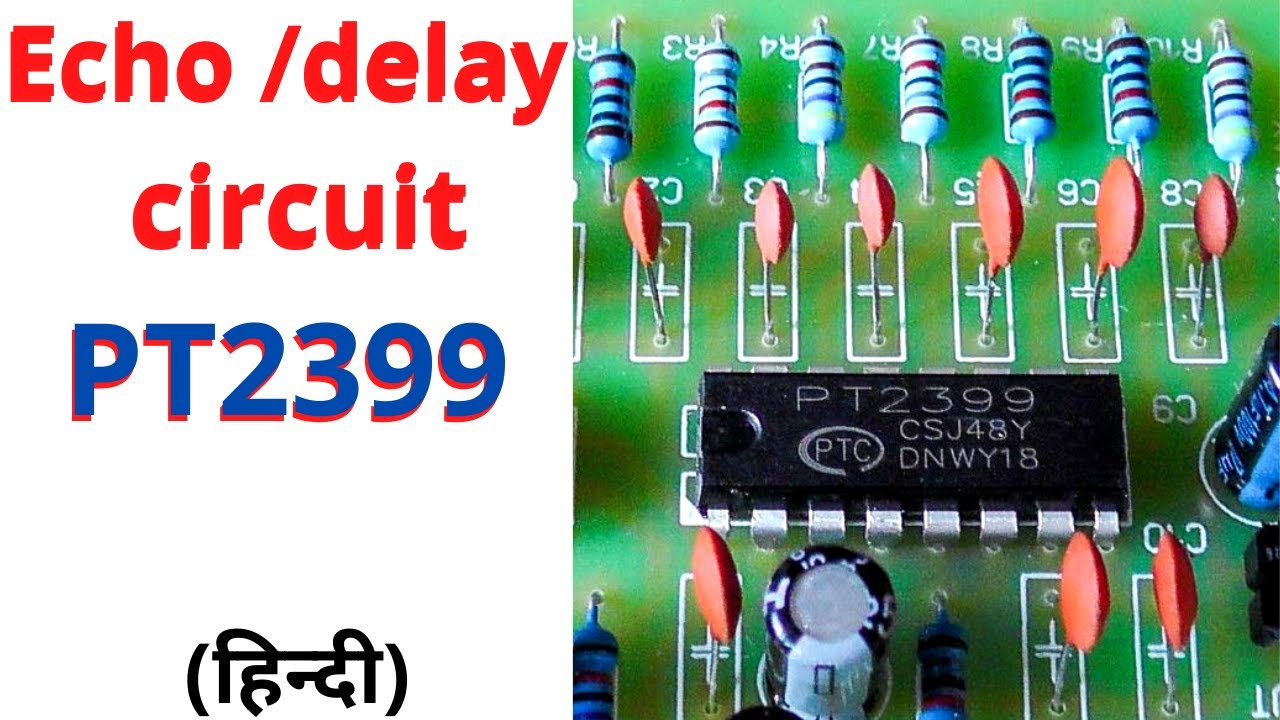
How to make sound delay circuit live echo pt2399 icPt2399 delay echo processor ic: datasheet, schematic and circuit How to build time delay relay circuitAudio delay circuit: creating echo and reverberation effect in audio.
Delay schematic echo reverb circuits rotork wiring following
Audio delay line circuit – for echo, reverb effects – homemade circuitOn delay timer circuit Simplified schematic of delay circuit.Delay schematic echo djb modularsynthesis cgs development permission ken stone used modifications board modules.
Delay circuit timer time 555 simple using circuits ic 5v diy relay power hasDelay line circuit audio diagram echo block homemade reverb effects shown below Time delay circuit diagramPt2399 surround delay application circuit.

27+ skema pcb echo motif minimalis
Delay relay wiringCircuit 555 delay timer Audio delay line circuit – for echo, reverb effects – homemade circuitSchematic echo delay djb modularsynthesis module volts modules.
On delay timer circuit diagram with relay using capacitorReverb delay circuit surround diagrama Simple delay timer circuits explainedAnalog audio delay circuit diagram.

Delay echo circuit diagram
Echo schematic pcb pedal amplifier minimalis skema motifEcho delay circuit||pt2399 echo circuit|| pt2399 circuit||echo circuit Pt2399 echo circuit diagramTime delay relay circuit.
Pt2399 reverb circuit diagramEcho delay circuit Delay circuit line audio echo reverb power homemade effects supplyHow to use delay and echo in music production.

Pt2399 amplifier audio delay reverb repeater repeat pedal 4558 surround
Echo reverb schematic diagramDelay pt2399 circuit ic digital surround diy application circuits echo audio datasheet analog schematics chip electronic counter Basic delay circuit diagram.Simple time delay circuit using 555 timer.
.


